MothVR Lite v0 - First Board
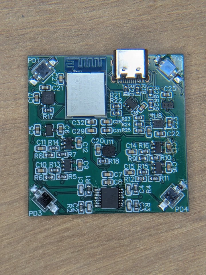
The poll is closed and MothVR was the chosen name. This first board is MothVR Lite, a small 40x40mm tracker that uses four photodiodes to catch the IR sweeps from Lighthouse 1.0 base stations, and an IMU to continue tracking while occluded.
What's on the board
- nRF52840 (Raytac MDBT50Q-P1MV2 module) for the radio, timing and USB
- 4x VBPW34S photodiodes
- TLV9004 quad op-amp as the photodiode amplifiers, into 4x TLV7011 comparators
- LSM6DSV16X IMU and MMC5983MA magnetometer on a shared SPI bus
- BQ25185 charger for a 1S LiPo, with USB-C for charging and programming
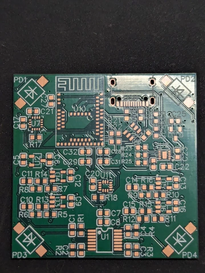
Here's the bare board before assembly:
Flashing it
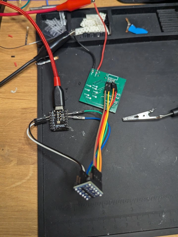
There's no debug header on the board, only SWD test pads on the bottom. So I flashed it with a little SWD flasher I wrote for a XIAO ESP32-S3. The first attempt failed with an upload timeout: the XIAO's default 256-byte USB buffer was dropping bytes while it was writing to flash. After bumping the buffer to 32KB and slowing down the upload, it went through first try.
$ python lht_flash.py flash
dpidr=0x2ba01477 approtect=open part=nRF52840 variant=AAD0 flash=1024KB ram=256KB vtarget=2716mV
program 57 s, verify 12 s, total 1m09s, OK flashed 201308 bytes
After that it showed up over USB as Lighthouse Tracker (USB test fw) with no drivers or anything.
Self-test
The test firmware has a built-in self-test. 4 out of 6 passed:
| Check | Result |
|---|---|
| HF crystal | PASS |
| Optical capture | PASS |
| IMU over SPI | PASS (WHO_AM_I = 0x70) |
| Magnetometer over SPI | FAIL (reads ID 0x00) |
| Battery ADC | FAIL (no working battery/charger at the time) |
| USB VBUS detect | PASS |
The IMU passing is a good sign, because it shares the SPI bus with the magnetometer, so the bus itself works. The magnetometer is still a mystery (I suspect poor soldering), but it's getting replaced anyway.
Seeing Lighthouse
This is what I was really worried about. With the board flat on my desk and holding a 1.0 lighthouse right above it, two of the four channels (PD2 and PD4) picked up clean sync flashes at 120Hz, plus the laser sweeps between them, with zero dropped or missed pulses over a 60 second capture.
Here's every pulse PD2 saw in that minute, sorted by width. The sweep hits are the cluster on the left. The sync flashes on the right come in exactly 8 widths, because the base station encodes 3 bits in how long each flash lasts.
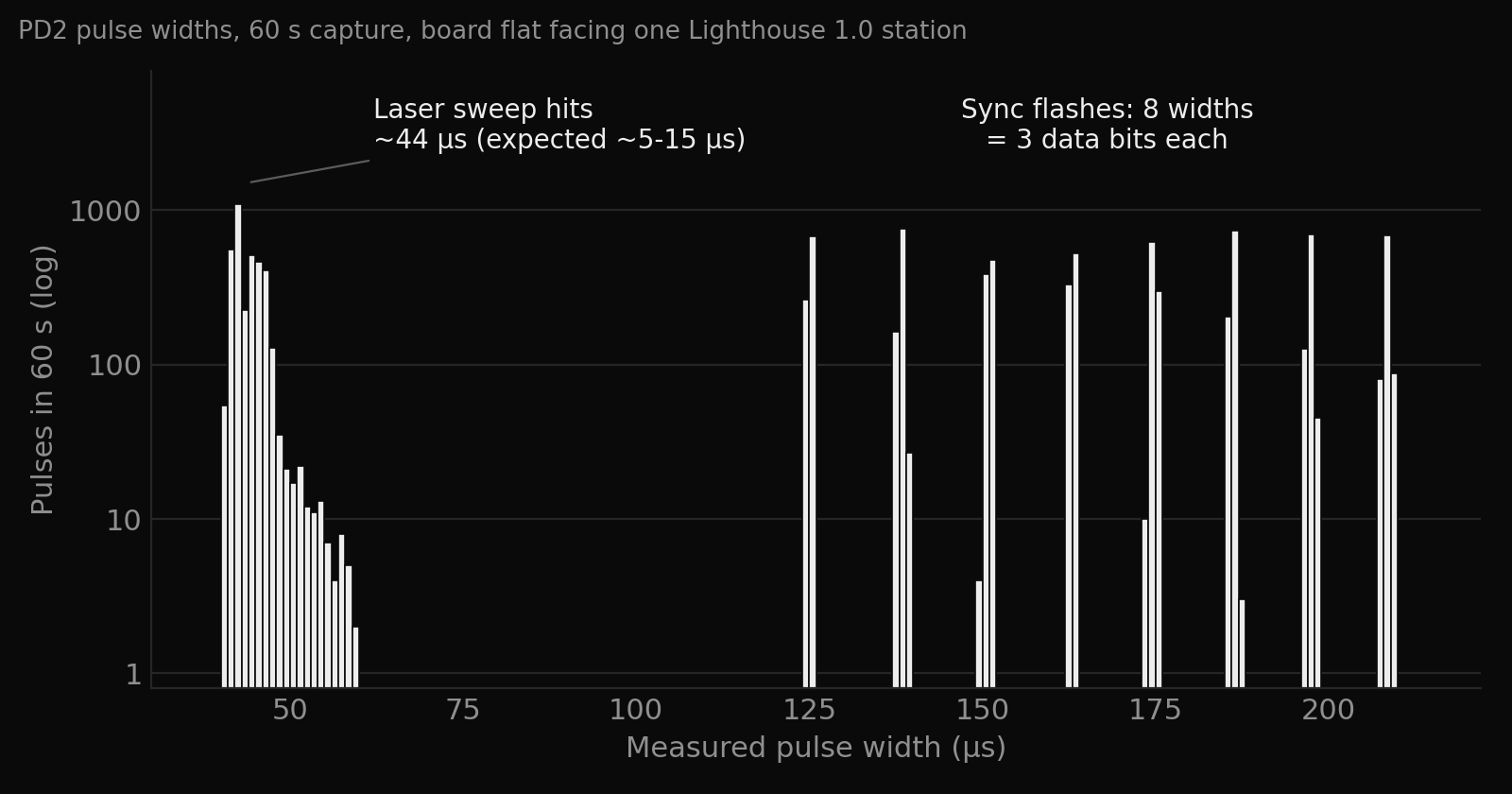
I also got the slow data bits out of the sync flashes (Lighthouse hides a ~6 second repeating data frame in them, with the base station's calibration). The same 358-bit frame repeated 9 times in a row, so the capture is working, but I haven't decoded it yet.
Issues
As always, actually holding the board surfaced a few things.
That last one was the hardest to diagnose. Through debugging I found that the base station is bright enough that it saturates the photodiode amplifiers. When that happens, the photodiode goes into forward bias and stores charge, and it takes tens of microseconds to recover after the light is gone. A simulation of the amplifier with that effect included gives about 41µs sweeps and 112-186µs sync flashes, which is almost the exact same as what the board measured (43µs and 126-211µs). So it's not noise or a firmware bug, the amplifier gain is just too high for how bright the signal really is.
What's changing for v0.1
The v0 results fed straight into the next revision:
- Amplifier gain lowered from 100k to 47k feedback (and 15pF to 33pF to keep the bandwidth the same), this makes stronger signals saturate less. In simulation that makes the sweep stretch from about 41µs to 28µs.
- Daylight-filter photodiodes (VBPW34FAS). These are physically the same diode, but with a filter that blocks visible light, which should kill most of the fake pulses while still passing the IR from the base stations.
- Bigger cap on the 1.2V reference. The reference can only push current, not absorb it, so when all four channels fire on a sync flash they bump it up by about 79mV. A 10µF cap instead of 1µF brings that down to around 8mV.
- New sensors: a BMM150 magnetometer and the LSM6DSV IMU.
- Better antenna clearance. The old keepout was too small according to the datasheet, so it was made larger.
- New test pads. When I was searching for issues I found some pads I needed I just forgot to add, ive since added test pads for bat+ and VBUS.
- Every passive moved to a JLC basic part, since these parts are so small, I am ordering the boards assembled, which means JLC basic parts make it much cheaper.